Application of Hekang Frequency Conversion Synchronous Control in Coal Mine Belt Conveyor
2021-08-25 14:06:36
1 Introduction With the wide application of frequency converters in various industries, the demand for high power drive systems has been raised in many industrial applications. However, a single motor has limited power due to its manufacturing and other reasons and cannot meet application requirements. In practice, two motors are usually used to drive a single device for drive control. In dual-motor synchronous transmission, the degree of balance of each motor load and the output power of the motor will directly affect the safety and reliability of the equipment operation. Hekang Frequency Conversion, with years of leading technology and practical experience, adopts master-slave synchronous control technology to distribute motor load and output power in a balanced manner, with reliable on-site operation and excellent control performance.
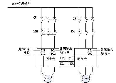
2 Synchronous control system scheme The design system framework is shown in the figure below:
If the master and slave are flexible connections, the slave adopts speed control. The master transmits its own running frequency and output current to the slave. The slave takes the received frequency as its own set frequency, and simultaneously outputs its own output current. The output current from the host is used to adjust the PI. The slave follows the master frequency and performs fine-tuning based on the difference between the master and slave loads to achieve speed synchronization and power balance. If the master and slave are rigidly connected, the slave adopts torque control. The master transmits its own operating frequency and output torque to the slave. The slave will receive the torque as its own set torque and will receive it. The frequency is used as its own output frequency to control the power balance of the two motors.
Any one of the two motors can be used as a master and the other is a slave. The CAN communication control mode is adopted between the master and slave. The communication speed can reach 1Mbps, which improves the dynamic response speed of the system. The CRC check is added to ensure that Data transmission accuracy.
3 Synchronous control of belt conveyors in a coal yard in Luzhou, Shanxi
Inverter Model: HID600A-T7-630G Low-voltage Inverter 2 Application Location: A coal yard in Shuozhou, Shanxi Province 3.2HID600A series high-power inverter master-slave control in a coal yard in Yanzhou, Shanxi, due to continuous increase in output, the original owner The capacity of the well belt conveyor has not met the current demand. In this retrofit project, the control scheme of the “One-for-One†dual-motor linkage of Hekang low-voltage inverter was adopted. The advantage of this solution lies in solving the power asymmetry distribution problem caused by working conditions, ensuring the uniform power balance of the two motors, and at the same time greatly reducing the impact of the motor start-up instant on the grid voltage.
The coal yard belt conveyor has a total of 2 driving motors, one of which is a main machine and the other is a slave. It belongs to a flexible connection. The belt has a certain degree of ductility. There is a certain speed error between the master and the slave. Therefore, the host uses SVC speed control, the slave also uses SVC speed control, and two HID600A-T7-630G inverters correspond to two drive motors. After the slave receives the host start command, it runs according to the output frequency of the master, adjusts its own output current with the output current of the host, adjusts the operating frequency automatically, synchronizes the speed of the master and the slave, and balances the power. The host's fault signal is interlocked with the slave's fault signal. Once any inverter fails, the entire system shuts down.
3.3 Commissioning Steps The system debugging mainly includes three parts: parameter self-learning, no-load debugging and load and commissioning.
1) Self-learning of motor parameters and no-load debugging Under the condition that the motor is not under any load, the motor parameters are set. A single inverter runs with the motor, and it first runs in the V/F mode. Set the frequency to 50Hz to observe whether the output current is normal in the acceleration, constant speed, and deceleration phases. At the same time, use the current clamp meter to measure the actual output current, and compare it with the inverter display current, and adjust the current detection through parameter adjustment. In the SVC mode, the parameters are self-learned. After the self-learning is completed, set different frequencies and observe whether the motor set frequency corresponds to the motor speed and whether the output current is normal.
2) Start with the load and debug two machines at the same time, first run the inverter with light load at 10Hz, check whether the output current, voltage and speed meet the requirements, and then run at 30Hz and 50Hz. If the light load process is normal, the normal production process can be commissioned. If there is an over-current or over-voltage fault in the light load process, the slave synchronous control parameters will be readjusted.
3.4 System Parameter Settings Table 3 Main Parameter Settings for Master-Slave Control
The system's inverter has many protection and fault output functions such as over-current, over-voltage, and communication failure. Without the common DC bus, the system can effectively guarantee the efficient and safe operation of the system.
4 Conclusion After using Hiconcom HID600A series PG vector-free synchronous inverters to control belt conveyors, the power factor and system efficiency of the system have been improved for several months, and the belt and mechanical transmission have been greatly improved. Embodies the following advantages:
1) The master-slave setting can be changed. Each inverter can be set as master or slave.
2) The master-slave fault interlocks, any one inverter fails, and the host computer automatically shuts down to ensure the system is safe and reliable.
3) High-performance SVC algorithm can ensure the smooth start-up and power balance of the belt conveyor. The output speed of the slave follows the master and the current is equivalent. From the keyboard to see the master and slave current difference of about 10A.
2 Synchronous control system scheme The design system framework is shown in the figure below:
Figure 1 master-slave control structure
In master-slave control, the host uses speed control, and the slave can use speed control or torque control. If the master and slave are flexible connections, the slave adopts speed control. The master transmits its own running frequency and output current to the slave. The slave takes the received frequency as its own set frequency, and simultaneously outputs its own output current. The output current from the host is used to adjust the PI. The slave follows the master frequency and performs fine-tuning based on the difference between the master and slave loads to achieve speed synchronization and power balance. If the master and slave are rigidly connected, the slave adopts torque control. The master transmits its own operating frequency and output torque to the slave. The slave will receive the torque as its own set torque and will receive it. The frequency is used as its own output frequency to control the power balance of the two motors.
Any one of the two motors can be used as a master and the other is a slave. The CAN communication control mode is adopted between the master and slave. The communication speed can reach 1Mbps, which improves the dynamic response speed of the system. The CRC check is added to ensure that Data transmission accuracy.
3 Synchronous control of belt conveyors in a coal yard in Luzhou, Shanxi
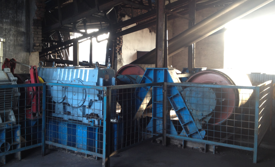
3.1 Live belt machine structure
Table 1 Motor parameters
rated power
500kW
Rated voltage
660V
Rated frequency
50Hz
Rated current
510.5A
Table 2 belt machine parameters
model
DTL120/100/2*500
captain
420 meters
bandwidth
1.2 meters
inclination
18°
Inverter Model: HID600A-T7-630G Low-voltage Inverter 2 Application Location: A coal yard in Shuozhou, Shanxi Province 3.2HID600A series high-power inverter master-slave control in a coal yard in Yanzhou, Shanxi, due to continuous increase in output, the original owner The capacity of the well belt conveyor has not met the current demand. In this retrofit project, the control scheme of the “One-for-One†dual-motor linkage of Hekang low-voltage inverter was adopted. The advantage of this solution lies in solving the power asymmetry distribution problem caused by working conditions, ensuring the uniform power balance of the two motors, and at the same time greatly reducing the impact of the motor start-up instant on the grid voltage.
The coal yard belt conveyor has a total of 2 driving motors, one of which is a main machine and the other is a slave. It belongs to a flexible connection. The belt has a certain degree of ductility. There is a certain speed error between the master and the slave. Therefore, the host uses SVC speed control, the slave also uses SVC speed control, and two HID600A-T7-630G inverters correspond to two drive motors. After the slave receives the host start command, it runs according to the output frequency of the master, adjusts its own output current with the output current of the host, adjusts the operating frequency automatically, synchronizes the speed of the master and the slave, and balances the power. The host's fault signal is interlocked with the slave's fault signal. Once any inverter fails, the entire system shuts down.
3.3 Commissioning Steps The system debugging mainly includes three parts: parameter self-learning, no-load debugging and load and commissioning.
1) Self-learning of motor parameters and no-load debugging Under the condition that the motor is not under any load, the motor parameters are set. A single inverter runs with the motor, and it first runs in the V/F mode. Set the frequency to 50Hz to observe whether the output current is normal in the acceleration, constant speed, and deceleration phases. At the same time, use the current clamp meter to measure the actual output current, and compare it with the inverter display current, and adjust the current detection through parameter adjustment. In the SVC mode, the parameters are self-learned. After the self-learning is completed, set different frequencies and observe whether the motor set frequency corresponds to the motor speed and whether the output current is normal.
2) Start with the load and debug two machines at the same time, first run the inverter with light load at 10Hz, check whether the output current, voltage and speed meet the requirements, and then run at 30Hz and 50Hz. If the light load process is normal, the normal production process can be commissioned. If there is an over-current or over-voltage fault in the light load process, the slave synchronous control parameters will be readjusted.
3.4 System Parameter Settings Table 3 Main Parameter Settings for Master-Slave Control
Host parameters
Slave parameters
function code
Parameter Description
Parameter value
function code
Parameter Description
Parameter value
F0.01
No PG vector control
0
F0.01
No PG vector control
0
F0.02
Terminal operation instruction
1
F0.09
Maximum operating frequency
51Hz
F0.03
Primary frequency source X selection
0
F7.10
Free stop
1
F0.08
Keyboard setting frequency
50Hz
FC.00
Speed ​​control/power balance selection
2
F0.09
Maximum operating frequency
50Hz
FC.01
Master-slave mode selection
2: This machine is a slave
F7.10
Free stop
1
FC.02
Master sends reference signal source selection to slave
1: host output current
FC.00
Speed ​​control/power balance selection
2
FC.03
Master-slave communication enable
1: Enable CAN communication
FC.01
Master-slave mode selection
1: This machine is the host
FC.04
Slave control command source selection
0: host communication control
FC.02
Master sends reference signal source selection to slave
1: host output current
FC.05
Slave reference frequency source selection
0: host communication control
FC.03
Master-slave communication enable
1: Enable CAN communication
FC.07
Slave reference signal source selection
0: Host communication given
FC.10
PID proportional coefficient
20000
FC.11
PID integration time
1
FC.18
PID control deviation limit
10
FC.19
PID adjustment characteristic selection
0: positive characteristic
FC.20
PID enable synchronous speed offline
5.0%
FC.21
PID enable
1: Enable
FC.22
CAN communication break time
0.0S
FC.23
PI limiter
2.0%
F0.12
acceleration time
0.01S
F0.13
deceleration time
0.01S
The system's inverter has many protection and fault output functions such as over-current, over-voltage, and communication failure. Without the common DC bus, the system can effectively guarantee the efficient and safe operation of the system.
4 Conclusion After using Hiconcom HID600A series PG vector-free synchronous inverters to control belt conveyors, the power factor and system efficiency of the system have been improved for several months, and the belt and mechanical transmission have been greatly improved. Embodies the following advantages:
1) The master-slave setting can be changed. Each inverter can be set as master or slave.
2) The master-slave fault interlocks, any one inverter fails, and the host computer automatically shuts down to ensure the system is safe and reliable.
3) High-performance SVC algorithm can ensure the smooth start-up and power balance of the belt conveyor. The output speed of the slave follows the master and the current is equivalent. From the keyboard to see the master and slave current difference of about 10A.
Problems associated with hard water:
Hard water and Skin - Dermatitis, Acne and Eczema
Hard water and Hair – Dull, stiff, fragile, breaking hair
Hard water and Cleaning - Soap not lathering, filmy and spotty glassware, issues with your laundry such as dullness in color, stiffness in fabric etc.
Hard water and Appliances - Scale builds up on shower head, in coffee boiler, dishwasher and plumbing.
Hard water and Water softener – Use Dr.Tim.Wang total hardness test strips to check effectiveness of your water softener or water filter pitcher
Water Hardness Test Kit,Soft Water Tester Strips,Universal Water Test Kit,Accurate Water Test Kit
Jilin Test Bio-Electron Co., Ltd , https://www.tst-check.com