Application of PXI Products in Multifunction Calibrator
2019-06-18 07:43:44
Key words: PXI products, multi-function calibrators, PXI technology I. Overview PXI technology is the product of the combination of CompactPCI and instrumentation and instrumentation technologies. With the development and release of the PXI 2.0 specification, PXI products are becoming more and more mature. There are more and more modules to choose from. Compared with traditional instruments, PXI products have the advantages of performance and volume, so it is very suitable for use in measurement and repair occasions that emphasize mobility (for example: application in the field of military inspection and repair In the article, this article takes the development process of the multi-function calibrator as an example to briefly introduce the related hardware and software components and applications of the PXI system.
The multifunctional calibrator under development is a portable testing device for on-site testing. The software and hardware structure is shown in Figure 1.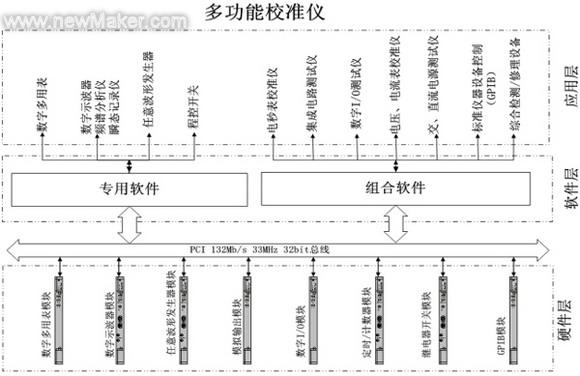
1, some modules through the use of special software, directly in the form of virtual instruments (such as: digital multimeter);
2. Different modules and dedicated adapters are combined together by combining software to complete other tasks assigned by the user (such as: electronic stopwatch calibration).
Second, system construction At the beginning of the system construction, the first is to select the PXI module that meets the needs. Requirements, performance, price, and service are the main reference factors for our selection. Starting from the actual needs of detection and repair, the current urgent need to solve the problem Have:
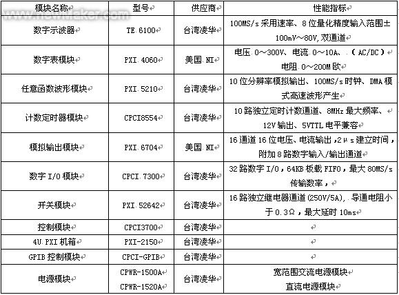
·Pointer type instrument calibration · Calibration of digital instrumentation · Electric stopwatch calibration · Power supply equipment testing · Instrumentation (weak current, low frequency) detection · Component function detection · Digital signal detection · Weaponry parts and accessories Inspections confirm the target through the market In the final investigation, we used PXI and CPCI products from various companies. The construction of the multi-function calibrator is shown in Table 1. This solution not only avoids the waste caused by one-sided pursuit of high performance, but also leaves some indicators. The margin is adjusted to the future development.
 In addition, in addition to the necessary chassis and control modules in the components of the multi-function calibrator, we have also purchased a wide range of AC/DC power modules to meet the requirements of military testing and repair to adapt to field or field test conditions. harsh environment.
The system programming uses NI LabVIEW software. Compared with VB and VC, the graphical programming tool LabVIEW is more suitable for the development of automated test systems. This is because NI is the initiator of the PXI specification and understands and supports the specification. Doing better, through VISA and the latest IVI driver technology, other company's PXI/CPCI products can also get better support in LabVIEW (in the driver for LabVIEW, ADLINK provides a more complete package in the form of Perfect hardware drivers. Those programmers who are familiar with VB and VC can control hardware directly in LabVIEW through DLL calls. These advantages are very attractive to users who need to build a comprehensive test system in a short time. of. The following figure is a comprehensive test software for the multifunction calibrator developed with LabVIEW.
(1) Software and hardware conflicts and solutions between modules;
Due to the adoption of module products from many companies, some modules may not work properly in the initial stage of system installation. For example, the 16-channel relay output module (52642) is a NI-IVI-driven PXI. The module installed the driver program in the order required by the user's manual. The Measurement & Automation Explorer (MAX) software provided with LabVIEW can't find the trace of the module. In the system's resource manager, the driver of the module is all normal. The arrival of the card is relatively late, before the installation of the chassis has other modules, in order to find out the reasons, then uninstall the 52642 module software driver, unplug all the unrelated modules, re-install the 52642 module in accordance with the requirements of the manual, the result is still the same, I decided to reinstall the operating system. After the installation of the operating system, the 52642 module was inserted first. After the software and hardware drivers were installed as required, the module finally appeared in MAX. At this point, everything was normal, and the remaining modules were inserted into the chassis one by one. , After installing the appropriate driver, test again found Completely normal arbitrary waveform generator TE5201 module completed work, with the first experience, reinstall the operating system, first insert the 5201 module, install the hardware driver and the corresponding software, the 5201 can identify and work, insert 52642 The modules were installed as required. After the system was started again, 52642 and 5201 were able to work normally. After installing other modules and corresponding drivers and supporting software one by one, the entire system was finally completely normal. A two-day hardship showed that the PXI system was under construction. In the process, especially when a number of company modules coexist, it is possible that abnormalities may occur during the installation of drivers according to conventional methods. In most cases, there is no problem with the module itself. The key is to carefully and patiently adjust the installation of modules and software. Order, more trials can often solve the problem; In addition, the installation of the module must be installed one by one test, although frequent shutdown, boot is too much trouble, but problems can be solved in time, or it may lead to unexpected accumulation of losses.
(2) Software development quick start:
In terms of software support, ADLINK has done relatively well. Not only does it provide hardware drivers in the form of development kits, it also provides source code routines for all popular programming languages, making it very easy for users to develop their own applications.
The system software of the multi-function calibrator was compiled using LabVIEW. Therefore, before the procurement, LabVIEW support was particularly emphasized. When we acquired the ADLINK product, we discovered that ADLINK had done a great job in driving, and finally only the digital oscilloscope. The module TE6100 needs to complete the control by calling the DLL form. Each board card ADLINK provides several sub-VI routines that are of great reference value. Through research routines, you can better help users master the control methods of the module. Some routines can be directly applied to your own design. It greatly reduces the difficulty of development and reduces programming time.
In a complex integrated system, how to embody humanized operations in software is a very important task. Taking the process of instrument calibration as an example, the verification procedures of the country need to be integrated into the program. Therefore, in the process of program preparation, an independent software module (such as environmental conditions and calibration data) is established in the form of subVIs for the commonality in the procedure. Processing, data saving and extraction, etc.) can be called at any time when required; the individuality in the procedure is fully displayed in front of the operator by means of dialog boxes, prompt boxes, wiring diagrams, etc. All work is clear and clear. In order to speed up the development of LabVIEW, we must first carefully analyze the system to find the most frequently used basic operations, and then turn these operations into subVIs that can be run independently; the second step is to combine these subVIs to form The more powerful modules; finally through the combination of modules to achieve a complex operation, and eventually form a complete integrated system. Since LabVIEW is a graphical programming tool, the programming of the program should follow the principle of simple and complex. It is recommended that during the process of programming, detailed work records should be made at any time. This will not only facilitate maintenance and expansion in the future, but also allow Others to read and modify. .
(3) PXI module calibration As a modular instrument, how to ensure the test accuracy is a user's concern, due to the module bias voltage, linear gain and other parameters will change with time, the environment, to bring errors to the measurement, so in large In most cases, the PXI module must be calibrated. The so-called calibration refers to the process of minimizing the measurement or output error through fine adjustment of the circuit. There are three ways to calibrate the PXI module:
1. Constant calibration method Some PXI boards were calibrated under standard conditions in the factory (such as ADLINK's TE6100 digital oscilloscope module) before delivery. Calibration constants used to correct errors were stored in the on-board non-volatile memory. Medium (EEPROM), can restore the state before leaving the factory by loading calibration constants. In addition to the permanent storage area of ​​the factory calibration data, the EEPROM of the PXI board also has a modifiable calibration data area for the user to use to save the factory calibration raw data or the user's own calibration data. The precision of the constant calibration is not high because it does not take into account the effects of time and temperature changes on the module measurement and output functions.
2. Self-calibration mode In order to reduce the measurement error due to offset and gain drift, some PXI modules provide 'self-calibration' function. Its working principle is: through the module's own high-precision onboard reference, in the calibration software control Next, test and correct any errors (such as NI's PXI6704 analog output module). The self-calibration of the module does not need to connect external signals, which is an effective way to improve the measurement accuracy and reduce the self-error.
3. The on-board reference used in the external calibration self-calibration is stable enough in most cases, but if it is in an extreme temperature environment or the calibration period exceeds one year, then an external calibration should be performed. External calibration refers to the calibration of the module using an external reference (instead of the on-board reference). External calibration usually recalibrates the on-board reference. The calibration result is stored in the EEPROM for later recall and external calibration. The use of an external reference to ensure that there is a sufficiently high accuracy, usually the external reference reference accuracy should be 3 to 5 times the module's own on-board reference, the external calibration is generally commissioned by the user commissioned by the calibration laboratory.
In the future, PXI products still have a long way to go in terms of enhancement of functions, improvement of drivers, and improvement of services. It is believed that with the advancement of technology, the application of PXI products will become more and more broad. The multi-function calibrator is an application attempt of PXI products in the field of military inspection. Because the project time is too hasty, the understanding and application of the module are limited, and the work is inevitably superficial. The experts in this article should be criticized and corrected.
The multifunctional calibrator under development is a portable testing device for on-site testing. The software and hardware structure is shown in Figure 1.
Figure 1, the functional structure of the multi-function calibrator
In the system, the PXI module is the most basic independent unit. Under the control of the software, each module can achieve certain functions. There are two ways to apply the module: 1, some modules through the use of special software, directly in the form of virtual instruments (such as: digital multimeter);
2. Different modules and dedicated adapters are combined together by combining software to complete other tasks assigned by the user (such as: electronic stopwatch calibration).
Second, system construction At the beginning of the system construction, the first is to select the PXI module that meets the needs. Requirements, performance, price, and service are the main reference factors for our selection. Starting from the actual needs of detection and repair, the current urgent need to solve the problem Have:
·Pointer type instrument calibration · Calibration of digital instrumentation · Electric stopwatch calibration · Power supply equipment testing · Instrumentation (weak current, low frequency) detection · Component function detection · Digital signal detection · Weaponry parts and accessories Inspections confirm the target through the market In the final investigation, we used PXI and CPCI products from various companies. The construction of the multi-function calibrator is shown in Table 1. This solution not only avoids the waste caused by one-sided pursuit of high performance, but also leaves some indicators. The margin is adjusted to the future development.
Table 1 Components of the Multifunction Calibrator
The system programming uses NI LabVIEW software. Compared with VB and VC, the graphical programming tool LabVIEW is more suitable for the development of automated test systems. This is because NI is the initiator of the PXI specification and understands and supports the specification. Doing better, through VISA and the latest IVI driver technology, other company's PXI/CPCI products can also get better support in LabVIEW (in the driver for LabVIEW, ADLINK provides a more complete package in the form of Perfect hardware drivers. Those programmers who are familiar with VB and VC can control hardware directly in LabVIEW through DLL calls. These advantages are very attractive to users who need to build a comprehensive test system in a short time. of. The following figure is a comprehensive test software for the multifunction calibrator developed with LabVIEW.
Figure 2 Comprehensive test software for multi-function calibration system
Third, the application of XI module application process, will inevitably encounter a variety of problems, the following is a summary of some experience in the development of multi-function calibrator, may be helpful to users engaged in the development of PXI systems. (1) Software and hardware conflicts and solutions between modules;
Due to the adoption of module products from many companies, some modules may not work properly in the initial stage of system installation. For example, the 16-channel relay output module (52642) is a NI-IVI-driven PXI. The module installed the driver program in the order required by the user's manual. The Measurement & Automation Explorer (MAX) software provided with LabVIEW can't find the trace of the module. In the system's resource manager, the driver of the module is all normal. The arrival of the card is relatively late, before the installation of the chassis has other modules, in order to find out the reasons, then uninstall the 52642 module software driver, unplug all the unrelated modules, re-install the 52642 module in accordance with the requirements of the manual, the result is still the same, I decided to reinstall the operating system. After the installation of the operating system, the 52642 module was inserted first. After the software and hardware drivers were installed as required, the module finally appeared in MAX. At this point, everything was normal, and the remaining modules were inserted into the chassis one by one. , After installing the appropriate driver, test again found Completely normal arbitrary waveform generator TE5201 module completed work, with the first experience, reinstall the operating system, first insert the 5201 module, install the hardware driver and the corresponding software, the 5201 can identify and work, insert 52642 The modules were installed as required. After the system was started again, 52642 and 5201 were able to work normally. After installing other modules and corresponding drivers and supporting software one by one, the entire system was finally completely normal. A two-day hardship showed that the PXI system was under construction. In the process, especially when a number of company modules coexist, it is possible that abnormalities may occur during the installation of drivers according to conventional methods. In most cases, there is no problem with the module itself. The key is to carefully and patiently adjust the installation of modules and software. Order, more trials can often solve the problem; In addition, the installation of the module must be installed one by one test, although frequent shutdown, boot is too much trouble, but problems can be solved in time, or it may lead to unexpected accumulation of losses.
(2) Software development quick start:
In terms of software support, ADLINK has done relatively well. Not only does it provide hardware drivers in the form of development kits, it also provides source code routines for all popular programming languages, making it very easy for users to develop their own applications.
The system software of the multi-function calibrator was compiled using LabVIEW. Therefore, before the procurement, LabVIEW support was particularly emphasized. When we acquired the ADLINK product, we discovered that ADLINK had done a great job in driving, and finally only the digital oscilloscope. The module TE6100 needs to complete the control by calling the DLL form. Each board card ADLINK provides several sub-VI routines that are of great reference value. Through research routines, you can better help users master the control methods of the module. Some routines can be directly applied to your own design. It greatly reduces the difficulty of development and reduces programming time.
In a complex integrated system, how to embody humanized operations in software is a very important task. Taking the process of instrument calibration as an example, the verification procedures of the country need to be integrated into the program. Therefore, in the process of program preparation, an independent software module (such as environmental conditions and calibration data) is established in the form of subVIs for the commonality in the procedure. Processing, data saving and extraction, etc.) can be called at any time when required; the individuality in the procedure is fully displayed in front of the operator by means of dialog boxes, prompt boxes, wiring diagrams, etc. All work is clear and clear. In order to speed up the development of LabVIEW, we must first carefully analyze the system to find the most frequently used basic operations, and then turn these operations into subVIs that can be run independently; the second step is to combine these subVIs to form The more powerful modules; finally through the combination of modules to achieve a complex operation, and eventually form a complete integrated system. Since LabVIEW is a graphical programming tool, the programming of the program should follow the principle of simple and complex. It is recommended that during the process of programming, detailed work records should be made at any time. This will not only facilitate maintenance and expansion in the future, but also allow Others to read and modify. .
(3) PXI module calibration As a modular instrument, how to ensure the test accuracy is a user's concern, due to the module bias voltage, linear gain and other parameters will change with time, the environment, to bring errors to the measurement, so in large In most cases, the PXI module must be calibrated. The so-called calibration refers to the process of minimizing the measurement or output error through fine adjustment of the circuit. There are three ways to calibrate the PXI module:
1. Constant calibration method Some PXI boards were calibrated under standard conditions in the factory (such as ADLINK's TE6100 digital oscilloscope module) before delivery. Calibration constants used to correct errors were stored in the on-board non-volatile memory. Medium (EEPROM), can restore the state before leaving the factory by loading calibration constants. In addition to the permanent storage area of ​​the factory calibration data, the EEPROM of the PXI board also has a modifiable calibration data area for the user to use to save the factory calibration raw data or the user's own calibration data. The precision of the constant calibration is not high because it does not take into account the effects of time and temperature changes on the module measurement and output functions.
2. Self-calibration mode In order to reduce the measurement error due to offset and gain drift, some PXI modules provide 'self-calibration' function. Its working principle is: through the module's own high-precision onboard reference, in the calibration software control Next, test and correct any errors (such as NI's PXI6704 analog output module). The self-calibration of the module does not need to connect external signals, which is an effective way to improve the measurement accuracy and reduce the self-error.
3. The on-board reference used in the external calibration self-calibration is stable enough in most cases, but if it is in an extreme temperature environment or the calibration period exceeds one year, then an external calibration should be performed. External calibration refers to the calibration of the module using an external reference (instead of the on-board reference). External calibration usually recalibrates the on-board reference. The calibration result is stored in the EEPROM for later recall and external calibration. The use of an external reference to ensure that there is a sufficiently high accuracy, usually the external reference reference accuracy should be 3 to 5 times the module's own on-board reference, the external calibration is generally commissioned by the user commissioned by the calibration laboratory.
In the future, PXI products still have a long way to go in terms of enhancement of functions, improvement of drivers, and improvement of services. It is believed that with the advancement of technology, the application of PXI products will become more and more broad. The multi-function calibrator is an application attempt of PXI products in the field of military inspection. Because the project time is too hasty, the understanding and application of the module are limited, and the work is inevitably superficial. The experts in this article should be criticized and corrected.
Three System Flat Knitting Machine
Flat Knitting Machine,3g Three Sweater Knitting Machine,Automatic Sweater Computerized Flat Knitting Machine
NINGBO YONGFU TEXTILE MACHINERY CO., LTD. , http://www.nswinders.com