Adjustment of machining center rotary table
Most machining centers are equipped with a rotary table (as shown in Fig. 1d), which allows the machining of multiple machining surfaces in one installation of the part. How to accurately measure the center of rotation of the rotary table in the machining center has an important influence on the quality of the parts being machined. The horizontal machining center is taken as an example to illustrate the measuring method of the rotation center of the worktable.
The rotation center of the table is at the center point of the upper surface of the table. As shown in Figure 1.
There are many ways to measure the rotation center of the table. Here we introduce a more common method. The tools used are: a standard mandrel, dial indicator, gauge block.

Fig. 1 The position of the center of rotation of the rotary table in the machining center
1.X to the center of rotation measurement
The principle of measurement:
The centerline of the spindle coincides with the center of rotation of the table. The position of the centerline of the spindle is the position of the center of rotation of the table. The display value of the X coordinate is the distance X from the center of rotation of the table to the origin of the X-direction machine. . The X-direction position of the rotary center of the table is shown in Figure 1a.
Measurement methods:
1) As shown in Figure 2, the standard mandrel is mounted on the spindle of the machine tool, the dial indicator is fixed on the worktable, and the position of the dial indicator is adjusted so that the pointer points to the zero position at the highest point of the standard mandrel.
2) Withdraw the mandrel from the Z axis in the +Z direction.
3) Rotate the table 180 degrees, and then move the mandrel back to its original position in the -Z direction. See Figure 2. Observe the deviation indicated by the dial indicator and then adjust the X machine coordinate, and measure repeatedly until the table rotates to the 0 degree and 180 degree directions. The readings indicated by the dial indicator hands are exactly the same. Then the X direction displayed on the machine CRT is displayed. The coordinate value is the position of the table X toward the center of rotation.
The accuracy of the table X to the center of rotation determines the X-axis concentricity of the hole in the U-turn machined workpiece.

Figure 2 Measurement of the X-direction rotation center
2. Measurement of Y rotation center
Measuring principle: Find the distance Y0 from the upper surface of the worktable to the origin of the machine tool Y, that is, the position of the center of rotation of the Y-direction worktable. The rotary center position of the table is shown in Figure 1b.
Measuring method: as shown in Figure 3, first move the spindle along the Y direction near the predetermined position, gently insert the measuring block with your hand, and adjust the Y-axis position of the spindle until the gauge block is just inserted.
Y direction to center of rotation = Y coordinate displayed by CRT (negative value) - Gauge height dimension - Standard mandrel radius
Worktable Y affects the center of the machining hole on the workpiece to the high dimensional accuracy of the center of rotation.

Figure 3 Measurement of Y to the center of rotation
3. Measurement of Z-turn center
Measuring principle:
Find out the distance Z0 between the rotary center of the worktable and the origin of the Z-direction machine is the position of the turning center of the Z-direction worktable. The position of the rotary center of the table is shown in Figure 1c.
Measurement method: As shown in Figure 4, when the worktable is at 0 degrees and 180 degrees respectively, move the worktable to adjust the Z coordinate so that the reading of the dial indicator is the same:
Z-turn center = C-axis Z-axis coordinate value displayed by the CRT The accuracy of the Z-turn center affects the dimensional accuracy of the distance between the two ends of the machine when the machine boring machine works (under the premise of accurate tool length measurement). On the contrary, it can also correct tool length measurement deviations.
The center of rotation of the machine can be used as a reference for a period of time after a single measurement has yielded accurate values. However, with the use of machine tools, especially in the case of mechanical failures in the relevant part of the machine tool, it is possible to change the center of rotation of the machine tool. For example, when a machine crashes during machining and when the spindle nut of the machine loosens. Therefore, the center of rotation of the machine tool must be measured regularly, especially before machining relatively high-precision workpieces, in order to calibrate the center of rotation of the machine tool so as to ensure the accuracy of workpiece processing.

Figure 4 Measurement of Z-turn center
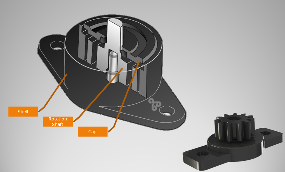
Rotary Damper with gear. Gear Damper is used to dampen drives, control speed, and many other applications. Gear dampers are widely used in automobile interior decoration, household electric appliances,etc. Gear damper increasing equipment life and reducing maintenance expenses.

NOTE:
1. Please contact the corresponding product engineer for specific torque products.
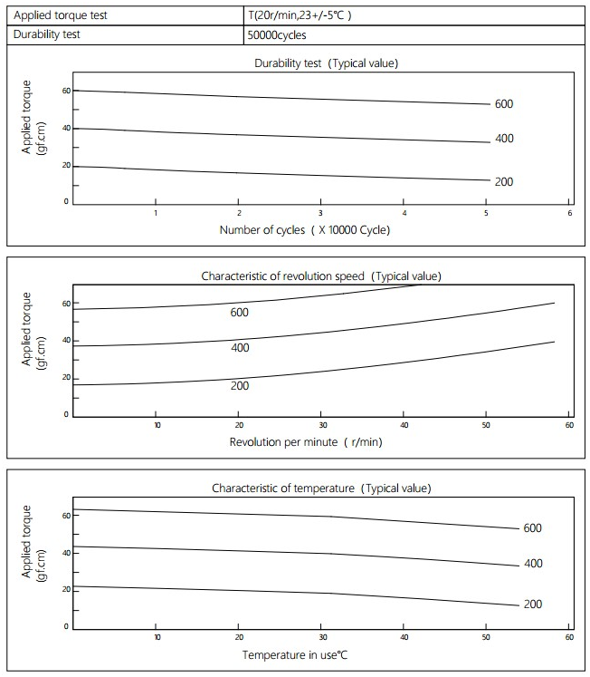
2. Max. rotation speed: 50r/min
3. Max. circle rate: 6 cycle/min(Clockwise360 °, 360 ° anti-clockwise for 1 cycle)
4.Operating temperature: -10~50℃
5.Storage temperature:-30~80℃

Applied torque: (T)
Test Temperature: 23+/-5℃
Rotating speed:20r/min
Durability test Method: Clockwise 360 °, 360 ° anti-clockwise
Rotating speed:20r/min
Test Frequency: 1cycle/min
Test Temperature: 23±5℃
Durability test cycle: 50000cycle
Test result criteria: Store in the room temperature for 24 hours or more after the test, recording to the torque T=T±30%T.
Gear Damper
Gear Damper,Hinge Dampers,Plastic Gear Damper,Small Rotary Gear Damper,Decoration Gear Damper
Shenzhen ABD Equipment Co., Ltd. , https://www.abddamper.com