Photovoltaic system cable design selection and construction
2019-12-05 11:03:25
In addition to major equipment, such as photovoltaic modules, inverters and step-up transformers, the photovoltaic cable materials used in connection with the construction of photovoltaic power plants are also responsible for the overall profitability, safety, and efficiency of photovoltaic power plants. With regard to the important role, the following is a detailed introduction to the uses and operating environments of the cables and materials commonly used in photovoltaic power plants.
The cables can be classified into DC cables and AC cables according to the system of the photovoltaic power station. They are classified according to their different uses and environments:
A, DC cable
(1) A series cable between components and components.
(2) Parallel cables between strings and their strings to DC distribution boxes (confluence boxes).
(3) The cable between the DC distribution box and the inverter.
The above cables are all DC cables. They are laid outdoors in large quantities and need to be protected from moisture, sunlight, cold, heat, and UV rays. In some special circumstances, they must also be protected against acids and alkalis.
Second, AC cable
(1) Connecting cable from inverter to step-up transformer.
(2) Connecting cable for step-up transformer to power distribution unit.
(3) The connection cable from the power distribution unit to the grid or user.
This part of the cable is an AC load cable, and there are many indoor installations. It can be selected according to the general power cable selection requirements.
Third, photovoltaic special cable
A large number of DC cables in photovoltaic power plants need to be laid outdoors, and the environmental conditions are harsh. The cable materials should be determined according to UV resistance, ozone, severe temperature changes, and chemical erosion. The long-term use of ordinary materials in this type of environment will cause the cable sheathing to be fragile and may even decompose the cable insulation. These conditions can directly damage the cable system, and at the same time increase the risk of short circuit of the cable. In the medium and long term, the possibility of fire or personal injury is also higher, which greatly affects the service life of the system. Therefore, it is very necessary to use photovoltaic dedicated cables and components in photovoltaic power plants. Photovoltaic-dedicated cables and components not only have the best weather resistance, UV and ozone resistance, but also withstand a wide range of temperature changes.
Fourth, cable design and selection principles:
(1) The withstand voltage of the cable must be greater than the maximum voltage of the system. Such as 380V output AC cable, to elect the 450/750V cable.
(2) The connection between the inside of the PV array and the square array, the selected cable rated current is 1.56 times the maximum continuous current in the calculated cable.
(3) AC load connection. The rated current of the selected cable is 1.25 times the maximum continuous current in the calculated cable.
(4) Connection of the inverter, the rated current of the selected cable is 1.25 times the maximum continuous current in the calculated cable.
(5) Consider the effect of temperature on the performance of the cable. The higher the temperature, the smaller the cable's current-carrying capacity, and the cables should be installed wherever possible for ventilation and heat dissipation.
(6) Consider that the voltage drop should not exceed 2%.
In operation, the DC loop is often affected by various unfavorable factors and causes grounding, making the system unable to operate normally. Such as extrusion, poor cable manufacturing, insulant material failure, low insulation performance, insulation aging of the DC system, or the presence of certain damage defects can cause grounding or become a grounding hazard. In addition outdoor environment small animals invade or bite can also cause DC ground faults. Therefore, in this case, armored, cabled with a rodent protection functional sheath is generally used.
Distributed photovoltaic common inverter cable selection:
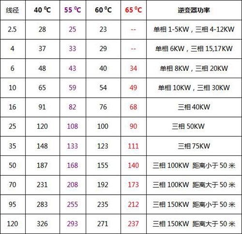
Distributed photovoltaic common inverter cable selection Note: The cable in the table is set according to the standard of the national standard copper wire.
If the cable length is greater than 50 meters, refer to the larger size cable.
V. Cable construction of photovoltaic power generation system
In the photovoltaic power generation project, the construction cost of the cable engineering is generally relatively large. The selection of the laying method directly affects the construction cost. Therefore, the rational planning and correct selection of the laying method of the cable is an important part of the cable design work.
1. Cable laying The cable laying method shall be based on the project conditions, environmental conditions, cable specifications, quantity, and other factors, and shall be selected according to the requirements of reliable, easy maintenance and technical and economical principles. The laying of DC cables for photovoltaic power generation projects mainly involves the laying of sand tiles, laying pipes, laying pipes, cable trenches, and laying tunnels.
The laying of AC cables is not much different from that of general power systems. DC cables are mostly used between photovoltaic modules, between strings and DC combiner boxes, and between combiner boxes and inverters. The cross-sectional area is small and the number of cables is large. Under normal circumstances, the cables are laid along the assembly brackets or directly buried through pipes. , DC cables generally need to be considered when laying:
(1) Connect the cable between the components and the connection cable between the string and the combiner box, use the component bracket as the channel support and fixing of the cable as far as possible, which can reduce the effect of environmental factors to some extent.
(2) The stress of cable laying should be even and appropriate, and should not be too tight. Generally, the temperature difference between day and night in photovoltaic sites is large, and the cable breakage caused by thermal expansion and contraction should be avoided.
(3) Photovoltaic material cable leads on the surface of the building should consider the overall aesthetics of the building. The laying position should avoid laying cables on the sharp edges of the wall and the bracket so as to avoid short circuit caused by cutting and grinding damage to the insulation layer or being cut off by the shear force. The wire caused an open circuit. At the same time, we must consider the issue of direct lightning strikes on cable lines.
(4) Reasonably plan the laying route of cables, reduce the crossover, and combine the laying as much as possible to reduce the amount of earth excavation and cable usage during the construction of the project.
The connection of cables The DC cables in photovoltaic power generation systems are mostly laid outdoors. The connection method is mainly based on connectors, which can be protected by wearing pipes. The component brackets are used as the channels for laying and fixing the cables to reduce the impact of environmental factors. The other cable connections are generally the same as the cable connections in the general power system.
Three Dimensional Mixer Main Feature:
1. As the mixing vat is able to have the multi-directional operations, there are more mixing points, so bring more favorable mixing effect. Its mixing homogeneity is much higher than that of general mixer, and the drug homogeneity error is lower than that of general mixer. Meanwhile, the max charging volume one time is higher than that of general mixer (The max charging volume of general mixer is 40% of full barrel volume).2. The mixing vat`s design is unique, its inner wall is fine polished, there is no dead angle, there is no pollution to the material, and the material will be discharged automatically by the gravity function without any residual, with advantages of pollution-free and residual-free. It is easy to discharge and clean.
3. The materials are mixed in the airtight space, so there is no pollution to the environment.
Technical Parameter
|
Model
|
EYH-300
|
EYH-600
|
EYH-1000
|
EYH-2000
|
EYH-5000
|
|
Barrel Volume(L)
|
300
|
600
|
1000
|
2000
|
5000
|
|
Max. Loading Volume(L)
|
150
|
300
|
500
|
1000
|
2500
|
|
Max. Loading Weight(kg)
|
75
|
150
|
250
|
500
|
1250
|
|
Rotary Motor Power(kw)
|
0.37
|
1.1
|
1.5
|
3
|
3
|
|
Sway Motor Power(kw)
|
0.75
|
1.5
|
1.5
|
4
|
4
|
|
Overall Size(mm)
|
2100*1200*1600
|
2250*1880*1915
|
2850*1465*1880
|
3565*1675*2300
|
4485*2110*2880
|
|
Approx. Weight(kg)
|
680
|
1300
|
2400
|
3010
|
4300
|

CHANGZHOU SULI DRYING EQUIPMENT CO.,LTD.specializing in the production of Mixing Dryer, Spray Dryer, Granulation Dryer ,Crushing Dryer, 3D Motion Mixer and V-shaped Mixer.
Three Dimensional Mixer,Three Dimensional Swing Mixer,Three Dimensional Mixer Equipment,Three Dimensional Powder Mixer
Changzhou Su Li drying equipment Co., Ltd. , https://www.sldrying.com