Design of Intelligent Open Channel Flowmeter
Open channel flowmeter is a flow meter for measuring the natural flow of free surface in non-full tubular open channels. It is widely used in urban water diversion canals, thermal power plant cooling water diversion and drainage, sewage treatment inflow and discharge canals, and industrial and mining enterprises wastewater discharge flow Measurement. Therefore, the development of an open channel flowmeter with low cost, high precision, easy operation and simple structure has important practical significance for the rational use of water resources and sewage treatment.
The flowmeter designed in this paper is based on the single-chip microcomputer C8051F060 as the main control chip, using its capture pulse width characteristics to achieve the flow rate signal acquisition and processing. The system has simultaneous measurement of liquid level, flow rate, and flow, and the data is displayed on the LCD screen; serial communication with the host computer through the RS-232 interface; plug-in U disk, to achieve massive storage; accurate real-time clock display; data is not easy Features such as loss of security storage.
1 Measurement principle
The flow measurement method used in this design is the “flow rate-water level calculation methodâ€. It measures a local (point, line, or small area) flow rate of the flow channel and represents the average flow velocity; the water level is measured again to obtain the flow area, and from the local flow velocity and average The relationship between the flow rate, calculated by calculation flow. The flow rate is measured using a propeller-type flow velocity sensor. The speed of the propeller of the flow velocity sensor on the flow path test section is firstly cycle-tested, and the signal obtained from the flow velocity sensor is generated by a mechanical contact or a reed-type relay contact. , Combined signal, the signal into the detection conversion circuit is converted into electrical signals, and filtered, debounced into a pulse signal, and sent to the I / O port of the microcontroller. Within a certain range, the propeller rotation speed and flow rate have the following linear relationship:
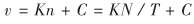 (1)
(1)
In the formula:
Ï… is the flow velocity at the measuring point;
n is the speed meter propeller rotation speed;
K is the proportional constant of the flow meter or the hydraulic pitch;
C is the minimum induction flow rate of the flow meter;
T is the time taken to measure the number of revolutions;
N is the number of rotations of the propeller in time T.
Therefore, in a certain period of time, as long as the number of revolutions of the propeller is measured, the instantaneous flow velocity at the propeller position can be obtained. Then, the flow rate and the flow area are integrated at each point of the test section to obtain the flow rate.
2 circuit design
The portable intelligent open channel flowmeter is based on the single-chip microcomputer C8051F060. It measures the number of revolutions of the propeller through the sensor, calculates the flow rate and the flow rate, and displays it in real time through the liquid crystal display. The required parameters are calculated, such as the hydraulic pitch coefficient, rotation. The rate, instrument drag coefficient, and measurement section are pre-set via the keypad. In addition, the entire system also has U disk read and write capabilities, real-time clock and serial non-volatile data storage capabilities. System block diagram shown in Figure 1.
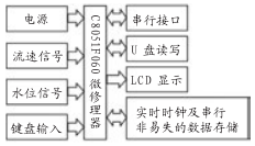
Figure 1 System Block Diagram
2.1 System Control Module
The system main control chip selects the highly integrated MCU chip C8051F060, which is a fully integrated mixed-signal system-on-chip (SoC) (System on chip) with a microcontroller compatible with the MCS-51 core and instruction set, in addition to the standard 8051 digital In addition to the components, analog components and other digital peripherals and functional components commonly used in data acquisition and control systems are integrated in the chip.
2.2 Signal Acquisition Module
Flow rate signal acquisition is achieved using propeller-type flow sensors. Each revolution of the propeller-type flow velocity sensor transmits one signal per revolution. The signal is a pulse signal. Using the capture function of the C8051F060, the pulse period is measured and the current flow rate can be calculated. The signal from the propeller-type flow sensor is sent to the T4EX terminal of the C8051F060 through the high-speed optocoupler 6N136. The T4 terminal is set to capture mode, T3 is set to the square wave output mode, T3EX is grounded, T3 is counted down, and T3 is connected to T4. Connect a 10kΩ pull-up resistor. When the signal received by T4EX is a falling edge, T4 generates a capture interrupt and queries through EXF4. When T4EX receives a signal pulse with a longer pulse width, T4 overflows. At this time, no capture occurs. In the interrupt, the overflow flag bit is cleared, the overflow count is incremented by 1, and the overflow count is recorded. A pulse is calculated based on the overflow count and RCAP4 value. The period, the total time accumulated by all the cycle time, using the formula into the data, you can obtain the flow rate.
Water level signal acquisition is achieved using a microphone pressure sensor.
2.3 Serial Interface Module
The system communicates with the PC through the RS-232 interface. The main control chip C8051F060 is powered by a 3.3V power supply. Therefore, the ADM202 is selected as the RS-232 level conversion chip. The chip supply voltage is 3.0V~5.5V.
The water level signal is measured using a microphone pressure sensor, which converts the water level into a 485 signal and sends it to the microcontroller. Therefore, the MCU needs to convert the 485 level before communicating with the microphone pressure sensor. The system selects the SN65LBC184 level conversion chip and uses the high speed optocoupler 6N136 in the RS-485 interface circuit to prevent the external signal from interfering with the system.
2.4 Other modules
(1) Keyboard input module. The system uses a 4×4 matrix keyboard and is connected with the P5 port of the single-chip C8051F060. It is used for the input of data such as the parameters of the propeller-type flow sensor, the modification of the clock time value, and the starting distance in the measurement process.
(2) U disk read and write modules. The system selects SL811HST chip of CYPRESS Company as the USB main control chip, communicates with C805lF060, realizes the correct read and write function of U disk. The C8051F060 communicates with the SL811HST through 8-bit bidirectional data lines D1-D7, chip select signal lines nCS, read nRD and write nWR input signal lines and an address line A0.
(3) LCD display module. The system chooses LM19264 dot-matrix liquid crystal module, this chip driver signal is 5V, need to add the level conversion chip between the one-chip computer and LM19264, choose the bidirectional conversion chip 74VLC4245, control the direction that the level shifts through the voltage level of the pin DIR.
(4) Real-time clock and serial non-volatile data storage module. The system needs reliable storage of the collected signals. In the case of power failure, the data cannot be lost. In the data acquisition process, data needs to be written and updated constantly; the system needs to be provided with a clock signal. In view of the above design requirements, the system uses RAMTRON's ferroelectric memory FM3164 to realize the functions of real-time clock and non-volatile data storage.
Construction Machinery Piston Pin including :Excavators Piston Pin,bulldozers piston pin,loaders piston pin,paving machines piston pin,cranes piston pin,and other heavy cargo etc.
Construction machinery piston pin material:Low carbon steel or low carbon alloy steel, such as 20, 20 mn, 15Cr, 20 cr or 20 MNV etc.
Construction machinery piston pin Advantage :Sufficient stiffness, strength and abrasion resistance.

Construction Machinery Piston Pin
Construction Machinery Piston Pin,Diesel Engine Piston Pin,Excavator Parts Piston Pin,Diesel Engine Part Piston Pin
Hebei Zhonghai Shipping Accessories Manufacturing Co., Ltd. , https://www.zhonghaiship.com