The use of electromagnetic flowmeters and analysis of electromagnetic compatibility
The measurement process of the electromagnetic flowmeter is not affected by the measured medium temperature, viscosity, density and other factors, and has the advantages of fast measurement speed, high precision, wide measurement aperture, good output linearity, no contact with the measured medium, corrosion resistance, and wear resistance. Due to its advantages such as low fluid pressure loss, it is widely used for the measurement of fluids such as pulp, additives, and water in paper mills. However, electromagnetic flowmeters also have their deficiencies, the sensor's output induced electromotive force is very small, susceptible to external electromagnetic interference, how to improve the electromagnetic flowmeter electromagnetic compatibility, so that it can be used in the harsh electromagnetic environment is the electromagnetic flowmeter design must be considered The problem. The article uses Yokogawa's ADMAGAE series of electromagnetic flowmeters as an example, combined with the author's engineering practice, introduces the use of electromagnetic flowmeters and analyzes their electromagnetic compatibility (EMC).
1 Working principle of electromagnetic flowmeter
The work of the electromagnetic flowmeter is based on the law of electromagnetic induction. That is, when a conductor moves in an electromagnetic field and the direction of motion is perpendicular to the electromagnetic field, an induced electromotive force is generated. The direction of the generated induced electromotive force is perpendicular to the direction of conductor motion and electromagnetic field motion. The magnitude of the induced electromotive force is proportional to the speed of the conductor and the magnetic induction of the magnetic field. When a conductive fluid passes through a pipe with an inner diameter of D(m) at an average flow velocity of V (m/s), if there is a magnetic field of magnetic induction B (T), a direction perpendicular to the magnetic field can be generated. Electromotive force E in the direction of fluid flow:
E=DVB (V) (1)
Volume flow Q is:
Q=Ï€D2V/4 (m3/s) (2)
Substituting equation (2) into equation (1) and processing it:
E=(4B/πD)×Q (V) (3)
If B and D are constants, it can be seen from Equation (3) that E is proportional to Q. The electromagnetic flow converter amplifies and converts the electromotive force E into a standard 4-20 mA signal or pulse signal, which is output as a corresponding flow signal.
2 electromagnetic flowmeter parameter setting method and configuration
Flowmeter parameter settings (configuration) There are two methods, one is to use the buttons on the display panel, the second is the use of handheld smart terminals.
2.1 Use the panel to set parameters
The symbols commonly used on ADMAGAE series electromagnetic flowmeter panels are:
(1) RED (red) does not light during normal operation and flashes when there is an alarm;
(2) The delimiter of the delimiter is indicated with a colon ":", indicating that the displayed data is in a state to be set;
(3) The unit display shows the unit of flow;
(4) The display data shows the type of flow data, setting data, and alarms;
(5) The decimal point represents the decimal point in the data;
(6) Setting keys These keys are used to change the type of data display and setting data. There are three types of data display types: flow data display mode, setting mode, and alarm display mode.
2.1.1 Traffic Data Display Mode
The flow data display mode represents the instantaneous flow rate and cumulative flow rate. ADMAGAE can display 12 types of flow data. Enter the flow display mode to change the display item with the “d1†parameter. For detailed settings, refer to the flowmeter user manual.
2.1.2 Setting Mode Setting Mode
Used to check parameter contents and rewrite data. Just press the "SET" key to recall this mode from the normal operating mode.
2.1.3 Alarm display mode
When the alarm occurs, the alarm mode will replace the current mode to display the type of alarm occurred, but this happens only when the parameter number is changed in the current flow display mode or setting mode (when the data item is in the Shows the alarm).
2.2 BT smart terminal settings
Instruments with intelligent communication capabilities can communicate with smart terminals. Yokogawa's smart terminals are BT100, BT200 and other models, referred to as BT smart terminals. They use the BRAIN protocol and superimpose a ±2mA, 2.4kHz modulation signal on a 4-20mA analog signal as signal transmission. Since the modulation signal is an AC signal, the superposition does not affect the value of the analog signal.
There are two ways to connect the BT intelligent terminal and the flowmeter: First, it is directly connected to the BT terminal under the end cover of the flowmeter. This method is suitable for on-site commissioning or the flowmeter does not have intelligent communication functions; the second is with 4 to 20mA DC signal cable connection, BT intelligent terminal can be connected from the control cabinet to the flowmeter signal line anywhere, the maximum distance of up to 2km, as long as the entire loop load resistance between 250 ~ 750Ω, you can reliably communicate. In this way, the operator does not have to go to the scene, and the flow meter can be set and monitored online in the control room, which is the most used method. BT intelligent terminal adopts the menu-type operation, and can display and modify various parameters of the electromagnetic flowmeter at any time. The basic operations include flowmeter self-test, range adjustment, display mode setting, and alarm setting.
2.3 electromagnetic flowmeter data setting and configuration
The electromagnetic flowmeter calculates the volume flow based on the minute electromotive force corresponding to the flow rate of the fluid and outputs a signal of 4 to 20 mA. In order to obtain the correct signal, three parameters must be set: path, flow range and meter factor. In these three parameters, the path and meter coefficients are set well before the instrument leaves the factory. Therefore, the user cannot set this parameter. Two parameters. The user can also set the flow range before the instrument leaves the factory. This setting can be reset only when the user requests to change the range.
3 Electromagnetic Compatibility Analysis
The work of electromagnetic flowmeter is based on the law of electromagnetic induction, and the induced electromotive force proportional to the measured flowrate is usually very small, and it is very vulnerable to external electromagnetic interference. The electromagnetic interference generated by itself is very small, so the electromagnetic flowmeter electromagnetic compatibility Sexuality is mainly reflected in how it works properly in a harsh electromagnetic environment. In the harsh electromagnetic environment, electromagnetic coupling electrostatic induction is the main source of interference noise of electromagnetic flowmeters; the electrochemical interference noise generated by the characteristics of the fluid being measured is the second source of electromagnetic flowmeter interference noise; the voltage of the electromagnetic flowmeter power supply Power supply disturbances such as frequency fluctuations are the third source of electromagnetic flow meter noise. To meet the EMC requirements of the instrument, smart electromagnetic flowmeters use hardware and software anti-jamming technology, respectively, in order to improve the electromagnetic flowmeter anti-jamming capability.
3.1 Characteristics of power frequency interference noise and electromagnetic flowmeter anti-jamming technology
The power frequency interference noise is firstly formed by the electromagnetic coupling of the electromagnetic flowmeter excitation winding and the fluid, the electrode, and the amplifier input circuit. The second is the power frequency common mode interference of the electromagnetic flowmeter work site, and the third is the power frequency train introduced by the power supply. Mode interference, etc., the physical mechanism they produce is the principle of electromagnetic induction.
Electromagnetic flowmeter magnetic field windings and fluid, electrode, amplifier input circuit electromagnetic interference generated by electromagnetic interference on the work of the electromagnetic flowmeter has the greatest impact, and in different excitation technology, its performance in different forms and characteristics, so take anti-jamming measures also different. Under the sine wave excitation magnetic field of the power frequency, this type of electromagnetic coupling power frequency interference noise manifests itself in the form of orthogonal interference, also called the transformer potential, characterized in that the amplitude of the interference noise is directly proportional to the excitation frequency of the power frequency sine wave, and the phase lags the flow signal. The potential is 90° and the magnitude is a few orders of magnitude greater than the flow signal potential [2]. DC excitation, low frequency rectangular wave excitation and dual frequency square wave excitation technology can basically eliminate the influence of orthogonal interference.
Common common-mode interference and power frequency series interference are two common types of interference, mainly due to electromagnetic shielding defects, distributed capacitive coupling, poor grounding of electromagnetic flowmeters, etc. Electromagnetic flowmeter adopts input protection technology and high input impedance. , High common mode rejection ratio, bootstrap preamplifier technology, and repeated grounding techniques improve the ability to withstand power frequency interference. ADMAGAE series electromagnetic flowmeters are equipped with a grounding ring. Their role is to establish a liquid grounding contact with the liquid, ensuring that the reference potential is the same as the liquid being measured, and to protect the flowmeter lining.
3.2 characteristics of electrochemical interference noise and electromagnetic flowmeter anti-jamming technology
3.2.1 Characteristics of Electrochemical Interference Noise
(1) Electrochemical polarization potential interference is caused by the electrode induced electromotive force polarization in the two poles, resulting in the polarization of the electrolyte at the electrode surface. Although the use of positive and negative alternating magnetic fields can significantly reduce the magnitude of the polarization potential, the polarization potential cannot be completely eliminated.
(2) Mud interference is the measurement of liquid-solid two-phase conductive fluid flow, when the solid particles or bubbles rub across the surface of the electrode, the contact surface electrochemical potential of the electrode suddenly changes, the electromagnetic flow sensor output signal appears spike-like interference noise.
(3) Fluid flow noise is measured when the conductivity of a low-conductivity liquid (below 100 μS/cm), the electrochemical potential of the electrode periodically fluctuates, resulting in a random interference noise with increasing frequency as the flow increases, with a similar mud disturbance 1/f Spectrum characteristics.
3.2.2 electromagnetic flowmeter anti-electrochemical interference technology
Electromagnetic flowmeter to improve the resistance to electrochemical interference in the measures taken mainly low-frequency rectangular wave excitation and dual-frequency excitation technology. Low frequency rectangular wave excitation not only has the characteristics of no eddy current effect and transformer effect (quadrature interference) due to DC excitation technology, but also has no polarization effect due to the power frequency sine wave excitation, which facilitates amplification of signal processing and avoids zero drift of the DC amplifier. , noise, stability and other issues have better anti-jamming performance. Although the low-frequency rectangular wave excitation has excellent zero stability, it can not overcome the mud disturbance and fluid noise interference in the measurement of liquid-solid two-phase conductive fluid flow containing fibers and solid particles such as mud and pulp. Research and analysis show that mud disturbance and flow noise have 1/f spectral characteristics. The amplitude at low frequencies is large, and the amplitude at high frequencies is small. If a low-frequency rectangular wave excitation with a higher frequency is used, the mud disturbance can be greatly reduced in magnitude. Therefore, increasing the excitation frequency helps to reduce mud interference and flow noise and improve the signal-to-noise ratio of the sensor output signal.
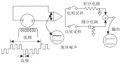
To sum up, to ensure zero stability of the electromagnetic flowmeter, it is best to use low-frequency rectangular wave excitation; in order to more accurately measure the flow of liquid-solid two-phase conductive fluid and low conductivity fluid, must use a higher frequency Rectangular wave excitation. The method of using the dual-frequency square wave excitation shown in FIG. 1 is the best solution.
3.2.3 Dual-frequency square wave excitation work and anti-jamming principle
An electromagnetic field containing two frequency components is formed in the measuring tube of the electromagnetic flowmeter: the high-frequency excitation component is not affected by the liquid disturbance, and the low-frequency excitation component has an excellent zero stability, and the component signals detected according to the high and low frequency timings After calculation, the flow signal can be obtained.
The principle of dual-frequency rectangular wave excitation measurement is shown in Fig. 1. An electromagnetic field composed of superimposed high- and low-frequency components is applied to the measured liquid through an excitation coil. The excitation waveform is superimposed on a low-frequency rectangular wave. The waveform of the rectangular wave at the electrical frequency. In the generated electromotive force, the low-frequency component obtains a stable flow signal with good zero stability through an integrating circuit with a large time constant. The low-frequency noise generated by the slurry or low-conductivity fluid can be suppressed by the high-frequency sampling circuit that is not affected by the noise. The flow signal having the same time constant passes through a differential circuit to determine the change of the flow rate signal, and the two different frequencies are The sampled signals combine to obtain a stable flow rate signal that is immune to noise and has a high zero stability.
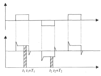
Electromagnetic flowmeters are generally powered by industrial-frequency AC power supplies. Both the amplitude and frequency of the power supply voltage will cause electromagnetic interference noise to the electromagnetic flowmeter. For the change of the amplitude of the power supply voltage, due to the use of multi-level integrated voltage regulator, in general, the change of the amplitude of the power supply voltage has little effect on the measurement accuracy of the electromagnetic flowmeter. When the frequency of the power supply voltage fluctuates, although its fluctuation range is limited, it has a great influence on the measurement accuracy of the electromagnetic flowmeter. In order to solve the problem of power frequency interference and achieve accurate measurement of the fluid flow induced potential eab signal, the following basic relationships should be used: 1 The excitation period is an integral multiple of the power frequency period, ie the excitation frequency is 50/nHz (n is even); 2 Positive and negative excitation of the same phase sampling. Fig. 2 is a typical potential signal form corresponding to the low-frequency rectangular wave excitation form. According to the above relationship, under an excitation period, if it is assumed that points t1 and t2 are equivalent interference points of power frequency interference and the sampling width T=T1=T2, The eab's basic formula is:
Equation (4) theoretically illustrates that the electromagnetic frequency flowmeter's power frequency interference can overcome the path, that is, synchronous sampling technology, which is based on the same phase (t1 = t2), the same width sampling (T1 = T2 = T) as the premise The sampling frequency should be chosen as an integral multiple of the power frequency period. In this way, even if an interfering signal is mixed, since its sampling time is a complete power frequency cycle, its average value is zero, and the interference voltage does not work.
4 electromagnetic flowmeter selection
4.1 General Principles of Electromagnetic Flowmeter Selection
(1) Whether the measured medium is a conductive liquid or a slurry, which determines whether or not to use an electromagnetic flowmeter;
(2) The conductivity of the measured medium determines the type of electromagnetic flowmeter—is it high or low conductivity?
(3) The maximum, minimum, and commonly used flow rate of process piping The nominal diameter of the process piping determines whether the flow rate of the medium is at a more economical flow rate point, whether the piping needs to be reduced, and finally the flowmeter diameter is determined;
(4) to determine the layout of the process piping, to determine the use of integrated or separate flow meter, as well as the protection level of the flow meter;
(5) Select the electrode type according to whether the measured medium is easy to crystallize or disintegrate;
(6) The electrode material is selected according to the corrosivity of the measured medium;
(7) The corrosivity, wearability, and temperature of the measured medium determine the lining material to be used;
(8) The maximum working pressure of the measured medium determines the nominal pressure of the flowmeter;
(9) The insulation of the process piping determines the type of grounding ring.
4.2 Selection according to the characteristics of electromagnetic flowmeter excitation method
(1) DC excitation type
This kind of electromagnetic flow meter has a very small quantity and is only used to measure the flow of liquid metal, such as mercury at room temperature and liquid sodium and potassium at high temperatures.
(2) AC power frequency excitation type
The earlier electromagnetic flowmeters were excited with 50Hz power frequency and were gradually replaced by low frequency rectangular excitations because of their vulnerability to electromagnetic interference and zero drift. However, when measuring liquid-solid two-phase flow such as mud and slurry, the low-frequency square-wave excitation method cannot overcome the spike noise generated on the surface of the solid wiper electrode, while the instrument of the industrial frequency AC excitation does not have this shortcoming, so there are still domestic and foreign Some electromagnetic flow meters still use AC frequency excitation.
(3) Low frequency rectangular wave excitation type
Because the low-frequency rectangular wave excitation mode consumes less power and the zero stability is good, it is currently the main excitation mode of the electromagnetic flowmeter. The waveform has two kinds of positive-negative and two positive-zero-negative-zero values. Some electromagnetic flowmeter excitation frequency can be set by the user. Generally, the small-diameter instrument uses a higher frequency, and the large-caliber instrument uses a lower frequency.
(4) Dual Frequency Excitation Type
The excitation current waveform is a high-frequency rectangular wave superimposed on a low-frequency rectangular wave. It is mainly used to overcome the slurry noise and flow noise in the presence of a binary square wave excitation, and to improve the stability and response characteristics of the instrument. Therefore, it is widely used in pulp and paper and sewage. Dealing with other industries.
5 Concluding remarks
Through the above analysis, the electromagnetic flowmeter has many advantages such as high measurement accuracy, high speed, easy use, wide measurement range, wide aperture, etc., but at the same time there are also measurement output signals that are vulnerable to power frequency electromagnetic interference, electrochemical noise of the fluid and power supply. Disadvantages of frequency changes. Electromagnetic flowmeters with different excitation modes have different anti-jamming technologies and applications. Correct understanding of the characteristics of various excitation technologies and the technical principles of different electromagnetic flowmeters is a prerequisite for the correct use of electromagnetic flowmeters.
Samarium Cobalt magnets are divided into 2 sort, SmCo5 & Sm2Co17, magnetization from axial direction or dia direction are both available, compared with SmCo5, Sm2Co17 magnets have reduced expensive samarium while the magnetism is rising, moreover, its`reversible temperature coefficient is also better than SmCo5 .For working temperature of SmCo magnet is up to 350℃,thus, its` chemical stability and BH use ratio are better than NdFeB in high temperature environment hence it is widely applied on AC servo motor, operator, industrial motor, sensor, aerospace and military areas,like cup magnet,round base magnet.


Smco Magnet,Strong Smco Magnet,Permanent Smco Magnet,Smco Magnet Disc,Irregular Smco Magnet,Smco Magnet Block,Cup Magnet,Round Base Magnet
NINGBO SHINE MAGENETIC TECHNOLOGY CO.,LTD , https://www.shinemagnets.com