Spherical surface error analysis and elimination method of CNC lathe
2025-10-12 04:05:11
When machining a spherical surface on a CNC lathe, several factors can influence the shape accuracy of the final product. One of the key error sources is the deviation of the tool tip from the spindle axis. This deviation can lead to significant form errors if not properly addressed. To better understand this issue, let’s examine the schematic in Figure 1.
In Figure 1, Y represents the offset of the cutting tool from the X-axis. Dt refers to the theoretical diameter of the AA section, while D is the desired ball diameter. The circular interpolation radius of the CNC lathe tool is R = D/2. In the AA profile, the tool's circular interpolation results in an elliptical shape with a major axis of D and a minor axis of D1. The resulting error is calculated as d = D - D1 = D - 2[(D/2)² - ∆Y²]¹â„².
In practical applications, the required diameter accuracy for the ball is often specified as ±0.005 mm, meaning that the error d should be limited to 0.01 mm. To achieve this precision, it is essential to control the value of ∆Y. Using the formula above, we can derive that ∆Y = ±½(2Dd - d²)¹â„².
For example, if D = 80 mm, then |∆Y| must be ≤ 0.63 mm to meet the required tolerance. One effective method to correct this deviation is the counter-knife approach, where the dial indicator reading directly reflects the ∆Y value.
Another important factor is the deviation of the tool’s circular interpolation center from the Y-axis, represented by ∆X. As shown in Figure 3, when machining a spherical surface, the actual diameter on the XOY plane is D/2, which corresponds to the circular interpolation radius. In this plane, the error is d = D1 - D = 2∆X. Similarly, in the XOZ plane, the error is also calculated as d = D1 - D = 2∆X.
To eliminate the impact of this error, the point-by-point comparison method can be used. By adjusting the tool compensation based on the measured error, the machining process can be fine-tuned. For instance, if the calculated error 2∆X is positive, a positive X-axis compensation (∆X) is applied. Conversely, if 2∆X is negative, a negative X-axis compensation is used, as illustrated in Figure 4.
During the roughing stage, the required inner ball diameter (D) is set, and a semi-finishing allowance of 1 to 1.5 mm is left. This means A1 = D - (1 to 1.5). By comparing the actual roughed diameter with the expected circular interpolation diameter A1, the error caused by the tool’s center deviation (2∆X) can be determined. Based on this, the appropriate compensation is applied.
For the finishing stage, a smaller allowance of 0.5 mm is left, making A2 = D - 0.5. After measuring and comparing, the same compensation method is applied until the desired spherical surface is achieved.
The machining of an outer spherical surface follows a similar process. The compensation direction remains the same, but the tool is installed in the opposite orientation. With modern CNC lathes, the pulse equivalent of the stepper motor can reach as high as 0.001 mm, allowing for precise circular interpolation with corresponding accuracy levels of ±0.01, ±0.005, or ±0.001 mm.
By selecting the appropriate CNC lathe based on the required part accuracy, manufacturers can ensure that all specifications are met efficiently and reliably. This detailed approach to error correction and compensation plays a crucial role in achieving high-quality spherical surfaces in CNC machining.
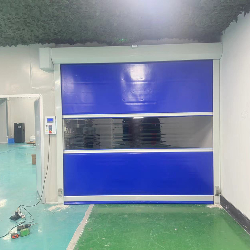
At our speed door manufacture center, we craft high-performance doors combining rapid cycle times, durable materials, and simple upkeep. Advanced sensors and self-repairing tracks ensure safe, uninterrupted operation. Custom sizes, colors, and controls fit any facility—logistics hubs, food plants, or production lines—boosting throughput while lowering costs.

PVC high speed door,plastic roll up doors,high speed fabric roll up doors,high speed rolling doors, pvc roll up doors
SHENZHEN HONGFA AUTOMATIC DOOR CO., LTD , https://www.hongfahsd.com